


Optimize Plastic Mold Fabrication with Dedicated Engineering and Quality Oversight
Optimize Plastic Mold Fabrication with Dedicated Engineering and Quality Oversight
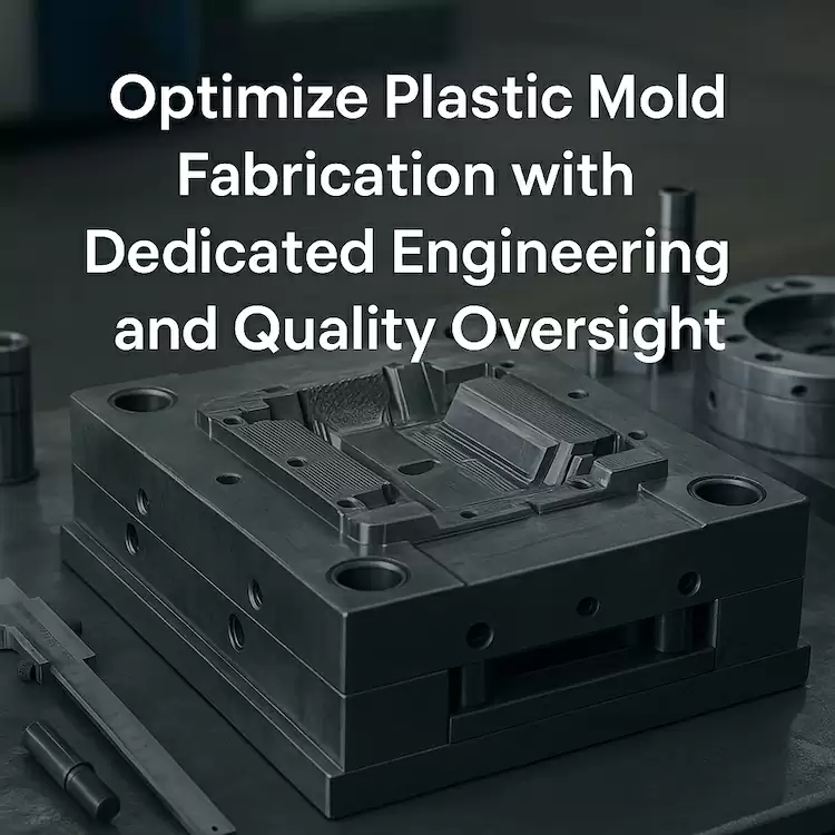
Optimize Plastic Mold Fabrication with Dedicated Engineering and Quality Oversight
Clear ownership • Fewer surprises • Tools that run right from T0
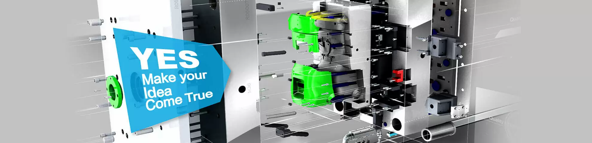
If your business depends on reliable plastic parts, your first priority should be the molds that make them. When tools are rushed, under-documented, or built without clear ownership, you pay for it later—in missed launch dates, flash, rework, and emergency welds on the bench.
This is why it pays to optimize plastic mold fabrication with dedicated engineering and quality oversight. Through the TaiwanMoldMaker.com network, you get a disciplined process from DFM to T1, backed by specialists who own the outcome, not just the machining.
Explore our end-to-end services:
Custom Mold & Design Maker → Mold Service → Injection Mold → Molding → Customer Examples → Contact
Why mold fabrication needs structured engineering control
Unplanned tool changes, weld repairs, and late design discoveries usually point back to early gaps:
-
CTQs and tolerance schemes not clearly defined on drawings.
-
No DFM or simulation for flow, cooling, or warpage.
-
Inconsistent steel selection or hardness for cores, cavities, and inserts.
-
Non-standard components that make assembly and maintenance harder.
-
Limited in-process inspection or metrology before the first trial.
Our approach is to give every tool a named engineering owner plus a quality owner who guide decisions, sign off on each stage, and control deviations before they become production problems.
Dedicated engineering: from concept to steel
Our engineering team leads mold fabrication through a repeatable, data-backed workflow:
-
48-Hour DFM & Risk Pack
-
Flow / cool / warp analysis on your 3D model.
-
Gate and runner proposal (valve vs. cold; hot-half brand suggestions).
-
Cooling layout and preliminary cycle model.
-
Parting-line, slide, lifter, and insert strategy.
-
Risk register with mitigation plan and open questions.
-
-
Standardized design rules
-
Uniform wall recommendations; ribs instead of mass.
-
Draft and radii guidelines for safe ejection and long tool life.
-
Preferred mold base and component libraries (MUD, DME, HASCO, etc.).
-
Steel and hardness map for cores, cavities, inserts, and wear components.
-
-
Design reviews with accountability
-
Formal sign-offs at design freeze, pre-machining, and pre-assembly.
-
Controlled ECN/ECR process so every change is recorded and traceable.
-
Result: machinists, EDM operators, and polishers work from clean, consistent data, while you have a clear view of how each engineering decision supports part quality.
Quality oversight throughout mold fabrication
Quality is not a final inspection—it's a series of gates embedded in the fabrication route:
-
Steel verification
-
Heat numbers, certificates, and hardness checks logged against the Tooling Dossier.
-
-
In-process metrology
-
Critical core/cavity features probed or CMM-checked before finishing and assembly.
-
Locating surfaces and shut-offs measured to prevent stack-up surprises.
-
-
EDM and polishing controls
-
Electrode libraries and wear compensation documented.
-
Defined polish steps for each finish (e.g. SPI A1, A2, B3) and protection protocols for finished surfaces.
-
-
Assembly & spotting checks
-
Blue-check contact patterns on shut-offs and parting lines.
-
Functional verification of slides, lifters, and core-pulls prior to full clamp-up.
-
-
Pre-T0 readiness review
-
Cooling circuits pressure-tested; hot-runner zones and thermocouples verified.
-
Safety interlocks, limit switches, and ejector strokes confirmed.
-
Every step is captured in a digital traveler so you can track who did what, when, and using which specification.
From first shot to production-ready tool
Dedicated engineering and quality oversight don’t stop when the mold leaves the toolroom. They continue through T0, T1, and ramp:
-
T0 trial (engineering focus)
-
Short-shot study to confirm flow and venting.
-
Weight ladder and gate-freeze to define pack/hold.
-
Cavity balance check for multi-cavity tools.
-
Early dimensional snapshot and cosmetic assessment.
-
-
Corrective loop
-
Vent adjustments, spotting refinements, minor geometry tweaks, texture/polish updates.
-
Weld repairs and insert changes documented in the Tool Change Log.
-
-
T1 trial (customer focus)
-
FAIR + CMM/scan against CTQs and GD&T.
-
Cosmetic map sign-off with photos and criteria.
-
Parameter set refined using scientific molding principles (V/P by pressure, cavity sensors where specified).
-
-
Hand-off package
-
Tooling Dossier (drawings, BOM, steel certs, torque map, cooling circuits, hot-runner data).
-
Trial Pack (T0/T1 settings, weight ladder, gate-freeze curves, cavity balance plots).
-
Maintenance Plan (shot-based PM intervals, consumable list, spare kit definition).
-
With these elements in place, your mold arrives at production with a known process window, not guesswork.
Connecting fabrication to MES and long-term performance
To truly “optimize” mold fabrication, you have to see how tools behave over time:
-
Each tool is assigned a unique ID tied to machine recipes, MES tags, and PM schedules.
-
Production data (OEE, scrap, down-time causes, kWh/kg) is analyzed by engineering and quality to spot recurring issues.
-
Findings feed back into future tool designs—for example:
-
Adding conformal-cooled inserts to problematic geometries.
-
Updating standard venting or slider designs.
-
Refining preferred steels and coatings for specific resin families.
-
In short, every mold becomes a learning input for the next generation of tools.
Example timeline with engineering & quality gates
A typical new tool program under this model might look like:
-
Day 0–2 – DFM & Risk Pack issued; review call with your team.
-
Day 3–7 – Design freeze; steel verification; rough and semi-finish machining; first metrology check.
-
Day 8–14 – EDM, finishing, polishing; assembly & spotting; hot-runner and cooling verification.
-
Day 15–17 – T0 trial in production resin; engineering corrections logged.
-
Day 18–22 – Adjustments (vents, shut-offs, polish, minor geometry); documentation updates.
-
Day 23–25 – T1 trial; FAIR + CMM/scan; cosmetic map sign-off; Tooling Dossier delivered.
-
Day 26+ – Optional PPAP or IQ/OQ/PQ; mold transfer plan if running in multiple plants.
Actual timing depends on part complexity, cavitation, resin, and validation scope—but the control points remain consistent.
RFQ checklist (copy/paste—this helps us optimize your mold from day one)
When you are ready to discuss plastic mold fabrication, include:
-
Target T1 and SOP dates, plus any PPAP or IQ/OQ/PQ expectations.
-
3D CAD (STEP/IGES) + 2D drawings with CTQs and GD&T clearly identified.
-
Expected annual volume and preferred cavitation (pilot vs. full production tool).
-
Required materials and alternates, including UL/FR/UV/food/medical requirements if relevant.
-
Cosmetic expectations (texture codes, colour standards, viewing zones).
-
Any existing corporate standards (mold base, component brands, documentation format).
-
Preferences for bridge tools vs. production steel, and whether future copy-cavity or multi-plant supply is planned.
Send your brief here → Contact
Why choose the TaiwanMoldMaker.com network
-
Dedicated engineering ownership on every tool from DFM through T1.
-
Embedded quality oversight in steel selection, machining, EDM, polishing, assembly, and trials.
-
Simulation-led, documentation-driven workflows that reduce errors and rework.
-
A clear path from first tool build to global, multi-plant production once your program scales.
Start here:
Custom Mold & Design Maker → Mold Service → Injection Mold → Molding → Customer Examples → Contact
